(en)Arduino Tutorial: Glockenspiel
Rédigé par lkiefer - - 1 commentaire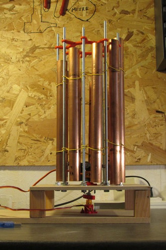
This project is inspired by «Copper Pipe Glockenspiel». For more information, please read the manual «Tubular Bell Chimes - Do It Yourself Handbook». I will explain you how to build an Arduino controlled «Glockenspiel». This instrument is not perfect because of the slow servomotors, but it is a good exercise to learn Arduino (we used it at our LUG).
I used 9 pipes to have 9 notes, but you can build it with more pipes and choose other notes: just pick the notes you want into the table, and adjust the «ecarteur» file and the sketch
Hardware
- Nano 3.0 Controller
- 2x 5V wall wart
- Two servos 9g / SG90
- 3D Printed parts
- Bearings : 3 Ø3 mm bearings (623zz) + 1 Ø 4 mm Bearing (624zz)
- 3 threaded rods M6, length 1 meter each
- 18 M6 nuts and washers
- 18 rubbers
- 3 screws M3x20 + 3 nuts + 4 washers
- 1 M4 screw + 3 nuts + 3 washers
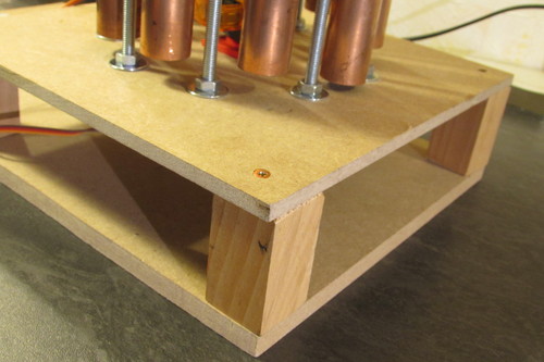
- Two MDF plates 20x20cm + 4 foots 5cm + 8 wood screws
- Metallic pipes (I used : 1.2m copper pipe Ø22x1)
- 12 wood screws (Ø3 x 25mm)
Tools
- A 3D printer
- PZ screwdriver, N° 10 wrench, plier
- Hacksaw, pipe cutter, grinder, sandpaper, a meter, a drill
- A computer or a smartphone with a tuner software
Define pipe length
We must define the length of the 9 pipes. The table below will help you in this behavior. If you use the same pipe as me (Ø22x1 copper), you may keep the table presets, otherwise you must enter your own values (length and frequency of your sample pipe).
First, cut a pipe piece length 250mm for example. To have a good sound, you must hold the piece at 22.4 % of its length from each side, for example with rubber : these are the last column values, which is 56mm for my 250mm piece.
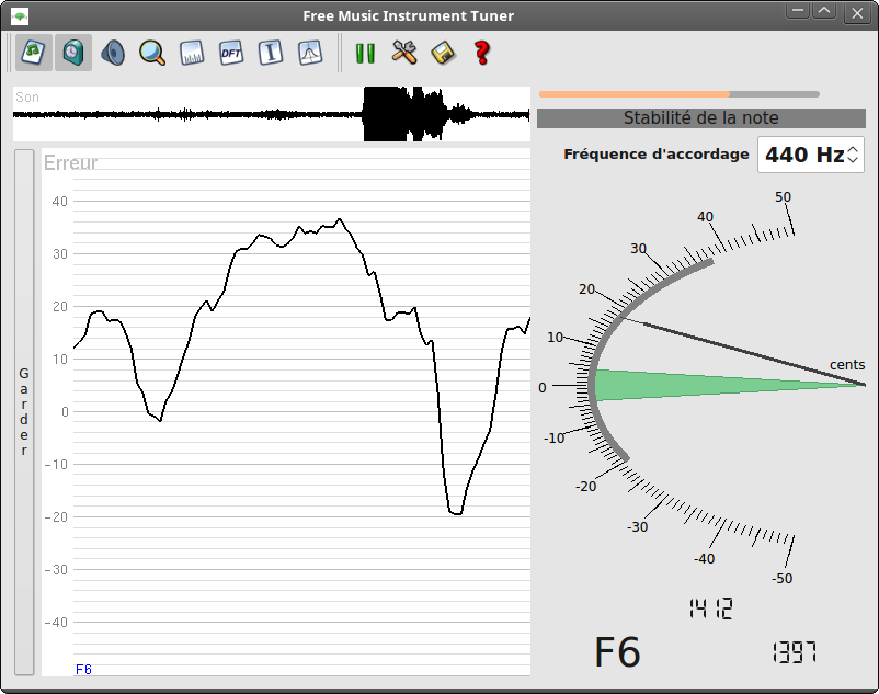
Measure the pipe frequency with the tuner software. I like to use fmit which is in my distribution Software Center. Once the software is loaded, hit the piece on its center. The software will shows some indications:
Real-time frequency (1412), the name of the closest note (F6), and the theoretical frequency of this note (1397). What we need is the average real-time frequency. Once you have it, you can fill the the form below with this frequency and the actual length of your pipe. Then you will have all the pipe length computed for your own material.
Theory
It is about how to compute the length by yourself. If you use the above table, you may skip this chapter.
The pipe resonance frequency depends of its diameter, its thickness, its material and its length: the only value you can modify is the length. Then the goal is to find the length of all your tubes to have the desired notes.
This is the mathematical formula which give you the frequency of a pipe:
f = A / L2
where f is the frequency (Hertz), A is a constant (mm2/s), and L is the length of your pipe. It is possible to compute A from the geometry and material of the pipe, but it's hard with custom material (see the manual for more details). Instead, we will infer A from L and f: L is the length of your sample pipe (250mm), and you will use the software to measure the frequency.
The last formula may be written this way :
A = f × L2
Replacing the f and L with the values, you would have something like:
A=1568 × 2502 = 98 000 000
Now that you have A, you can compute the length of all your pipes. Just select the frequency of the note you want, and place it in this formula :
L = v( A / f )
Tune the pipes
Cut the pipes with the computed lengths, a little bit taller. Put the pipes on a proper support, and measure their frequency. If the frequency is too low, slightly shorten the pipe, then measure the frequency again. Don't forget to tune your first sample pipe.
Assembly
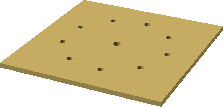
Take a wood plate (top), and find its center. Draw a 30mm circle on its center, then put the «ecarteur» on this circle. You will use this piece to draw the 9 Ø6mm holes you have to drill on the plate. Drill a hole on the center too.
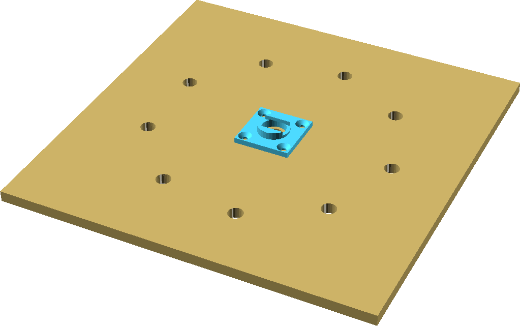
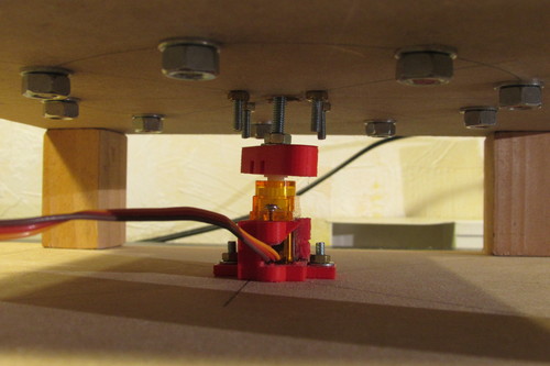
Put a bearing into the «palier» part, and fasten it on the plate center with 4 M3 screws (or with 4 wood screws)
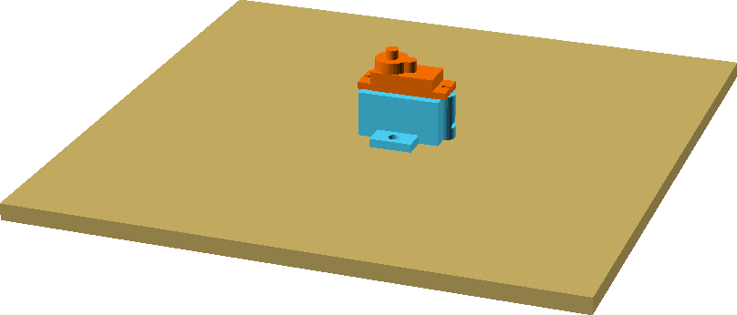
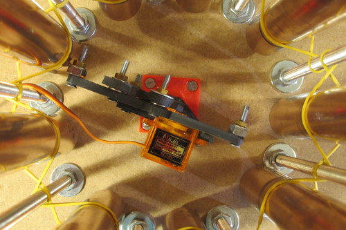
Take the other plate (bottom). Use the «support» piece to clamp a servo on it. Be sure the servo axis is on the plate center. Mounted on the servo axis, you must have the arm that fits into the «coupleur» part.

Grind the two sides of the M4 screw head, so that the screw fits into the «coupleur» and doesn't spin. Clamp the screw on the «coupleur» with a washer and a nut. Place the screw through the top plate and the «palier». Then, insert on the screw a nut, a washer, the «plateau» piece, a nut, and tighten them all.
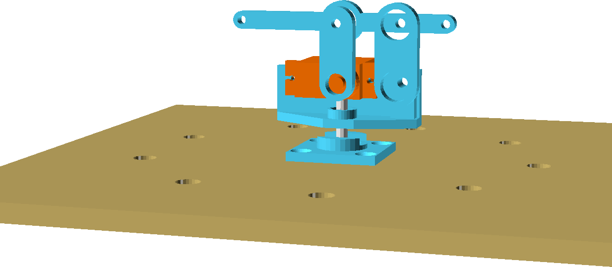
Finish the assembly with the Ø3 bearings, the «bras» and «bras2» parts, «tourelle», «marteau» and a servo. It may be better if you can add some nuts on the hammer endings.
Warning: the servo arm must be vertical when set at 90°. You can ensure that by using the «servo90» sketch.
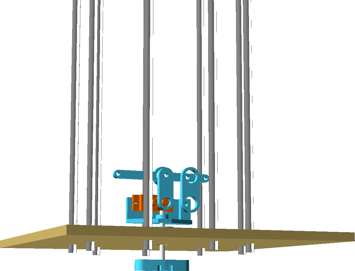
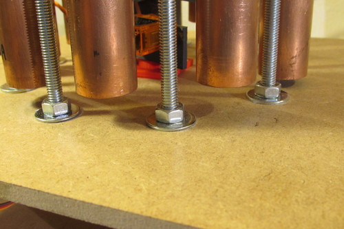
Cut the threaded rods 33cm long and tighten them on the top plate using two nuts and two washers for each chunk.
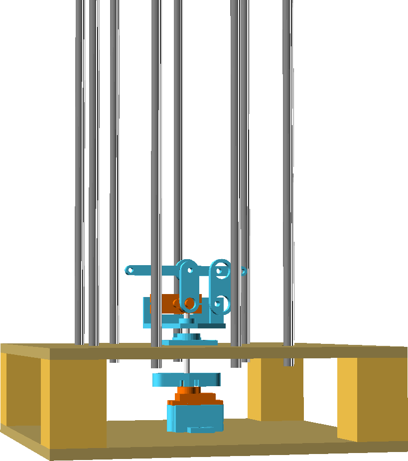
Clamp the four feet on the bottom plate using four wood screw. Place the top plate, ensuring that «axe» will fit on the servo. Clamp the plate with four screw.
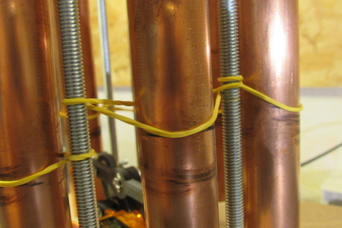
You must now place the rubbers! Start to insert the bottom rubbers across the rods, starting where the shortest pipe will be. Then, do the same with the top rubbers, starting from the same direction.
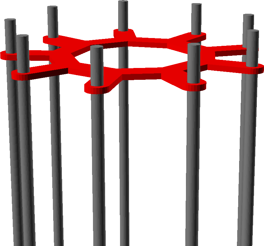
Put 9 nuts and 9 washers on the top of the rods, then insert the «ecarteur», and tighten it with another 9 nuts and washers

Now place the pipes through the rubbers, ensuring the rubbers are at the 22.4% position. The pipes must be aligned on the bottom, not touching the plate, so that the hammer can hit each pipe.
It's time to wire the servos. Connect the first servo «data» wire (bottom servo) to the Arduino pin #9, and the other servo «data» wire to the pin #3. The servos power wires must be connected to a dedicated power supply, because the servo can reach a consumption peak which is too high for the Arduino. Don't forget to connect the Arduino ground to the dedicated power supply ground, otherwise the Arduino cannot control the servos.
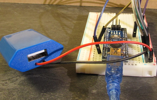
On the top of this article, I suggest you two wall warts: one can be connected on the Arduino USB cable, and the other should be a bit modified to add two wires that can be plugged on the servomotors (open it and sold the wires properly on the 0 and 5V pins).
Programming
Open the glockenspiel.ino sketch with the Arduino IDE. Be sure the servo library is already installed into your IDE.
These sketch allow you to play multiple melody on a row. Here are some explanations on how it works:
The notes1[] table contains all tube positions (from 0 to 180°). The pipes are 40° spaced, then it is easy to find all tube positions since you have the first. The taller pipe will be notes1[0].
The notes2[] table contains the hitting angle of servo2. The value is positive or negative depending the direction of the strike. You can adjust this value for each pipe, to compensate a bad alignment of the assembly.
Into the tableautemps[] table you will find the shortest note duration for each melody (each melody may have its own tempo).
The partition1[] table contains the notes to play number (from 0 to 8). If you have multiple melodies, add the note 9 between each melody.
The partition2[] tables is used to set the duration of each note. The shortest note will have a value of 1, and all others will be a multiple of this duration. Warning: You must add an extra value before each melody, in order to synchronize the two partition tables.
Code : glockenspiel.ino
#include <Servo.h>

Servo servo1;         // create servo1 object
Servo servo2;         // create servo1 object
int tempsretour=100;  // delay before the hammer return 90° (ms)
// Duration of the shortest note for each melody
int tableautemps[]={500,150,400};
int temps=tableautemps[0];

// Pipe position ( 0 to 180°)
unsigned char notes1[]={ 38,  78, 118, 158, 18, 58, 98, 138, 178};
// Angle of the stroke for each pipe (positive or negative depending of the direction of the stroke)
char          notes2[]={-26, -26, -26, -26, 36, 36, 36,  32,  22};

// Sorted list of pipes to stroke
char partition1[]={    // Jingle Bells
                   6,6,6,
                   6,6,6,
                   6,8,4,5,6,
                   7,7,7,7,6,6,
                   6,5,5,6,5,8,
                   6,6,6,
                   6,6,6,
                   6,8,4,5,6,
                   7,7,7,7,6,6,
                   8,8,7,5,4,

                   9,  // Brother John
                   0 ,1 ,2 ,0 ,
                   0 ,1 ,2 , 0,
                   2, 3, 4,
                   2, 3, 4,
                   4, 5, 4, 3,
                   2, 0,
                   4, 5, 4, 3,
                   2, 0,
                   7, 4, 7,
                   7, 4 ,7,

                   9,  // Twinkle, Twinkle, Little Star
                   0,0,
                   4,4,5,5,
                   4,3,3,
                   2,2,1,1,
                   0,4,4,
                   3,3,2,2,
                   2,1,4,4,
                   3,3,2,2,
                   2,1,0,0,
                   4,4,5,5,
                   4,3,3,
                   2,2,1,1,
                   0};

// Notes durations (multiples of "temps")
char partition2[]={1,1,1,2,
                    1,1,2,
                    1,1,1,1,4,
                    1,1,2,
                    1,1,2,
                    1,1,1,1,2,2,
                    1,1,2,
                    1,1,2,
                    1,1,1,1,4,
                    1,1,2,
                    1,1,1,
                    1,1,1,1,4,

                     1,
                     4,4,4,4,
                     4,4,4,4,
                     4,4,8,
                     4,4,8,
                     3,1,2,2,
                     4,4,
                     3,1,2,2,
                     4,4,
                     4,4,8,
                     4,4,8,

                     1,
                     1,1,
                     1,1,1,1,
                     2,1,1,
                     1,1,1,1,
                     2,1,1,
                     1,1,1,1,
                     1,1,1,1,
                     1,1,1,1,
                     1,1,1,1,
                     1,1,1,1,
                     2,1,1,
                     1,1,1,1,
                     2};

void setup() {
  servo1.attach(9);  // servo 1 is wired on pin 9
  servo2.attach(3);  // servo 2 is wired on pin 3
  servo2.write(90);
  delay(temps);
}

void loop() {
  char musique=0;
  int i = 0;
  while  ( i < sizeof(partition1)) {
    if(partition1[i]==9){
      musique++;
      delay(3000);
      temps=tableautemps[musique];
    }
    else{
      frapper(partition1[i],partition2[i]);
    }
    i++;
  }

  delay(3000);
  musique=0;
  temps=tableautemps[0];
}

void frapper(char note, char duree){
  if (duree==0){
    duree=1;
  }
  servo1.write(notes1[note]);
  delay (duree*temps-tempsretour);
  servo2.write(90+notes2[note]);
  delay(tempsretour);
  servo2.write(90);
}
Code : servo90.ino
#include <Servo.h>
// Use this sketch to center the servo axis
// so that you can properly mount the arm on it

Servo servo1;

void setup() {
  servo1.attach(3);  // Wire the servo on pin 3
  servo1.write(90);
}

void loop() {
}
Ways to improve the device
- Raise the hammer so that it strokes the pipes on their centers
- Improve pipes clamps
Pictures
#1 - InfoLibre a dit :